
In the two previous posts, we examined the increase of trans-Atlantic cable system capacity and assessed whether this increase could meet forecasted bandwidth demand. The answer to this question? More cable systems are required across the Atlantic Ocean, as current technology does not offer enough cable capacity growth.
In this post, we will review the cable system technologies that were gradually introduced in order to increase cross-sectional cable capacity across transoceanic routes.
Subsea Cable Technology Timeline
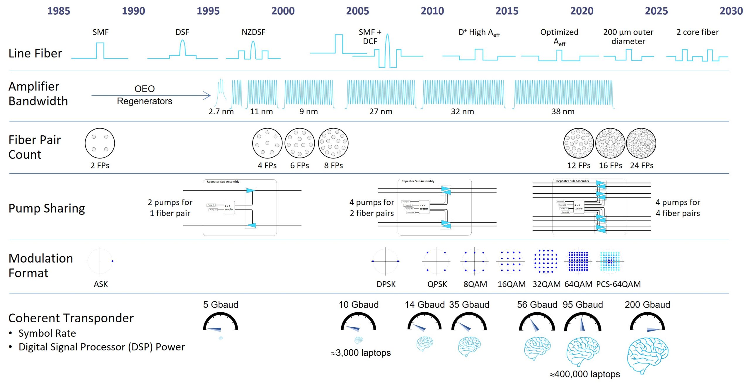
In the figure above, the Pioneer team has identified and selected six key technologies that directly impact the total capacity a subsea cable system can achieve. Fueled by regular discussions with the subsea industry suppliers, the figure shows the approximate dates of introduction of these technologies in commercial transoceanic cable systems.
Line Fiber: The characteristics of the line fiber heavily impacts the capacity achievable by a cable system over a given transmission distance. One key characteristic is the linear fiber attenuation – the higher the fiber attenuation, the more repeaters are needed in the cable system. An alternative approach would be to increase the repeater total output power at the expense of higher fiber nonlinearities (and higher power consumption). The intensity threshold beyond which fiber nonlinearities turn into significant transmission impairments can be raised with large effective area fiber to the detriment of high fiber loss sensitivity on microbending. Optical fibers with up to 150-µm² effective area have been used between 2016 and 2018 across the Atlantic Ocean. The current trend is to use 80- to 110-µm² fibers.
Practical high-end optical fibers offer attenuation as low as 0.154 dB/km in a loose environment, as found in the central area of submarine cable mechanical structure. An attenuation of 0.154 dB/km corresponds to a 50% decrease in signal power after 20-km fiber propagation. A similar attenuation of 50% is observed through only 5 cm (or 2 inches) of standard glass used for house windows. This comparison highlights the exceptional quality and purity of the silica material used for ultra-low-loss submarine fibers.
For chromatic dispersion, current coherent systems are based on highly positive dispersive fiber, with no more need for cumbersome in-line chromatic dispersion compensation management.
Amplifier Bandwidth: Continuous improvement in the performance of gain flattening filters (with wider bandwidth and lower insertion loss error function) and the yield of their manufacturing has been a challenge in the industry for many years. Today, the optical amplifiers built in the submerged repeaters offer a flattened gain over typically 38 nm of The physics of erbium ions in silica material does not allow to significantly increase the amplifier bandwidth in the 1528-1568 nm region (the so-called conventional band or C band).
Erbium-doped fiber amplifier technology, however, makes the opening of a second optical amplification window possible, ranging from about 1570 to 1610 nm. This new spectral window is called long (L) band as it accommodates longer wavelengths than those of the C-band.
Only one cable system, the Pacific Light Cable Network – PLCN trans-Pacific cable, announced in 2016 and put in commercial service in 2022 – has been deployed with C+L band EDFA technology. The industry walked away from the C+L technology and preferred to follow the so-called C+C approach with a higher fiber pair count and C-band amplification window.
Fiber Pair Count: According to the Shannon Law: per fiber capacity grows logarithmically with Optical Signal to Noise Ratio (OSNR) and linearly with bandwidth of the transmission channel. Large OSNR comes with fiber nonlinearities, which can be only partially compensated for today. In addition to this, the logarithmic dependence of capacity on OSNR makes this approach less power efficient – doubling the repeater pump power does not double capacity. On the other side, doubling the fiber bandwidth (using wider bandwidth repeater) or the cable bandwidth (using more fiber cores) linearly increases the cable capacity and leads to power efficient cable systems operating at relatively low.
High Fiber Count (HFC), aka Space Division Multiplexing (SDM), approach is the current industry strategy to increase the cross-sectional cable capacity. HFC/SDM directly translates into more optical fiber pairs housed in the cable structure, compared to the pre-2020 norm of a maximum of eight fiber pairs. To avoid the redesign of the central tube, some cable manufactures employ optical fibers with reduced outer diameter (e.g., 200 µm² vs 250 µm² for standard fiber coating) for offering 24 fiber pairs.
Pump Sharing: Pump redundancy is an old concept in submarine cable systems. Inside an amplifier pair (one unidirectional amplifier per each transmission direction of a fiber pair), the optical pump power used to be delivered by a couple of pump sources combined using an optical 2×2 coupler.
To further reduce the impact from one pump source failure, more optical pump sources can be combined to feed more amplifier pairs. A common implementation is to group four pump sources and share the combined optical pump power to two or four amplifier pairs. In the case one of the pump sources fails, the remaining pump power will be decreased by only 25%. This modest pump power fall will translate in a less than 25% decrease in the repeater output power, which will quickly recover along the cascade of amplifiers that are operated in saturated gain regime.
Additionally, pump sharing applied to high fiber count system allows for more efficient use of the pump available in each repeater, compared to the maximum per fiber capacity.
Modulation Format: Due to the practical symbol rate limits imposed by optical and electronic components technology, there was a need before 2010 to increase the number of bits per symbol for achieving the high bit rates required by the most capacity-hungry users. Increasing the number of symbols (i.e., increasing the symbol alphabet size) raises the number of bits that are transmitted per symbol in one clock period. Combining phase and amplitude modulations (nQAM for quadrature amplitude modulation with n symbols), a larger symbol alphabet and more bits per symbol can be achieved using various types of modulation formats. Today, commercial transmission equipment for submarine cable systems uses modulation formats up to 64QAM.
More recently, transmission equipment vendors have proposed Probabilistic Constellation Shaping (PCS) to allow variable symbol rates with a fine granularity and offer improved tolerance to fiber nonlinearities.
Coherent Transponder: In the past 26 years the symbol rate has increased from 5 giga symbols per second (5 x 10⁹ symbols per second or 5 Gbaud) to about 100 Gbaud. At the same time, coherent transponders include more and more powerful Digital Signal Processors (DSPs) to fulfil numerous functions including:
- Chromatic dispersion compensation
- Clock recovery
- Polarization mode dispersion compensation
- Differential encoding
- Phase cycle slip mitigation
- Soft-decision forward error correction
- Probabilistic constellation shaping
- Symbol mapping and de-mapping
- Nyquist spectrum shaping
- Digital sub-carrier multiplexing
Current DSPs are based on the latest semiconductor manufacturing processes, with an average half-pitch length of 7 nm. With a processing power equivalent to about 400,000 laptops, recent DSPs for coherent optical transmission led to high per fiber capacity at a lower cost per transported bit.
In the next post we will compare, or rather confront, this subsea cable technology timeline with the temporal evolution of trans-Atlantic cable capacity.
For comments or questions, please contact us: [email protected].